mobi.doc
Introduction
Documentation of the documentation station for the do•doc app.
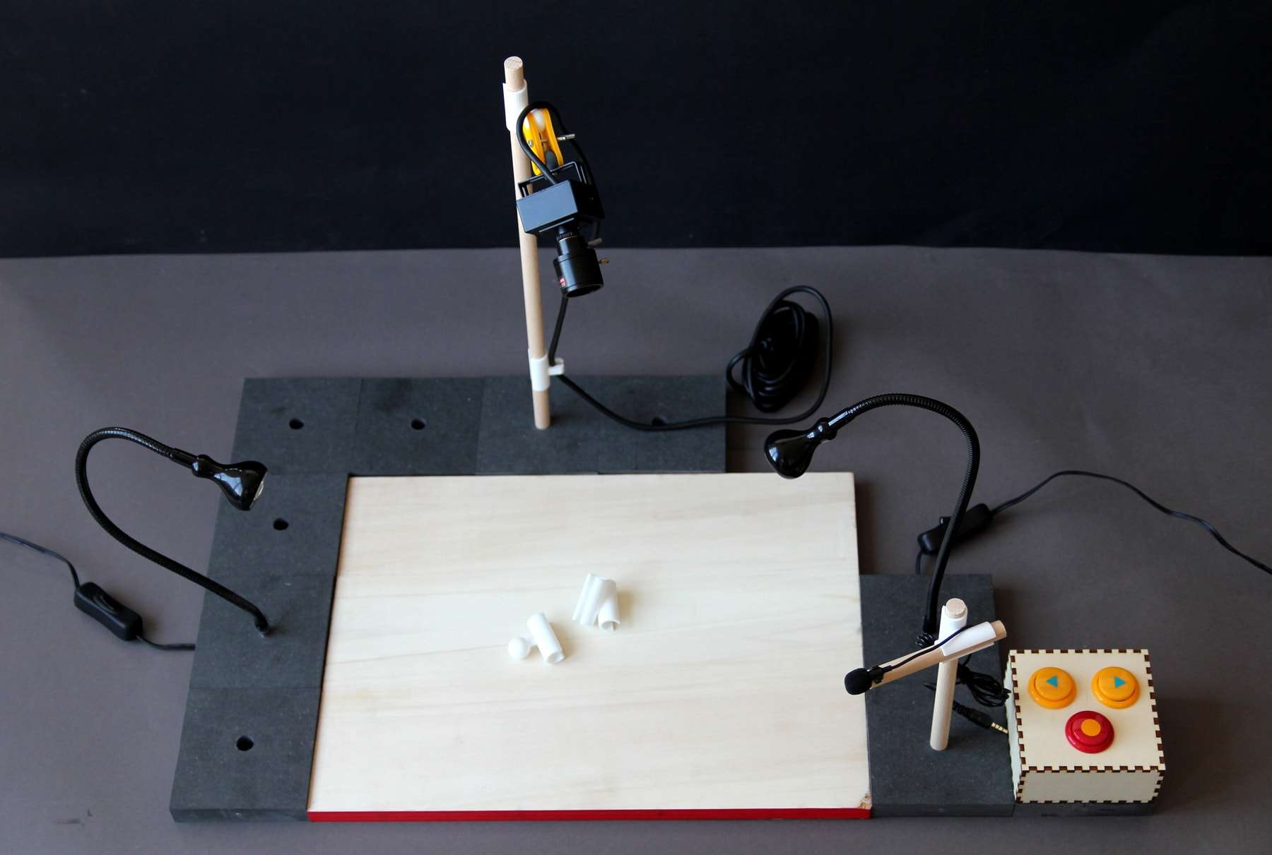
mobi.doc is under the free license CC BY-NC-SA, which means that anyone can download the files, follow the instructions to build their own station, modify it and share it again as long as it is not used commercially (for example, selling the 3D parts or the instructions themselves). Credits must remain clearly visible, including if you share these instructions after modifying them.
Tools and Materials
Materials
For the board
- a birch plywood or MDF board, 30 x 40cm and 19mm thick, for the board.
- adhesive whiteboard film on a roll, to cut and stick on one side of the board: on Amazon
- 6 square tiles, 10 x 10cm and 19mm thick, in through-colored grey MDF (for example the one from Leroy Merlin)
- 38 magnets: at Supermagnete
- 5 wooden dowels of different lengths, 12mm in diameter, fluted or not, for example at Leroy Merlin
- 4 3D printed parts (3 parts with a 90° angle, 1 with a 45° angle) – see the chapter Making the 3D parts
- 1 phone holder, bought or 3D printed – see the chapter Making the 3D parts
- a webcam (for example a Logitech c920 or a camera without autofocus)
- two desk lamps with adjustable arms
- a microphone, for example this one
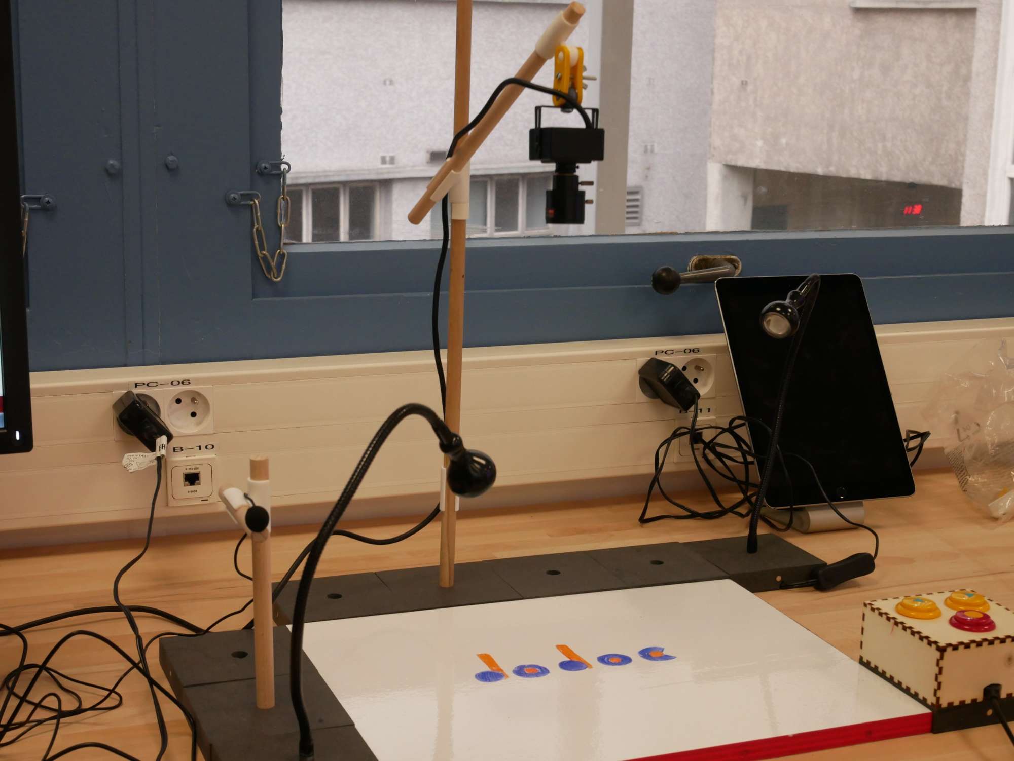
For the Dodoc box (on the right in the photo above)
- a 3mm MDF sheet
- 3 arcade buttons, for example on AliExpress
- 1 Arduino with an ATmega32U4 (Leonardo or Micro for example)
- jumper wires or cable
- Arduino USB cable
Tools
- Laser cutter
- 3D printer
- A soldering iron
- Wood glue
Making
Making the box

-
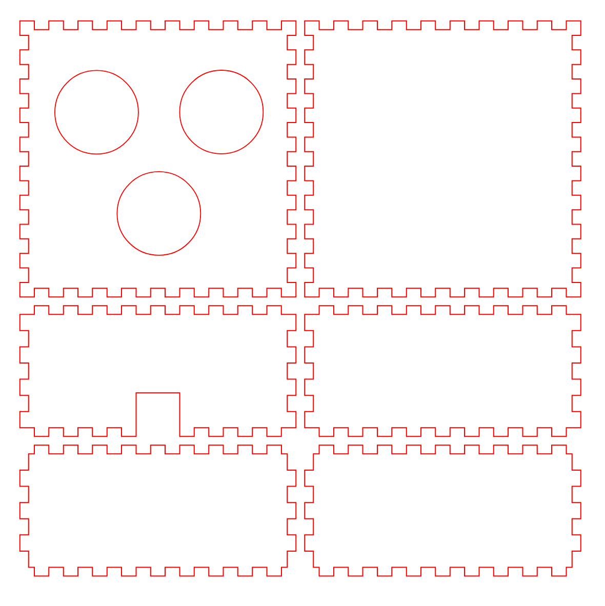
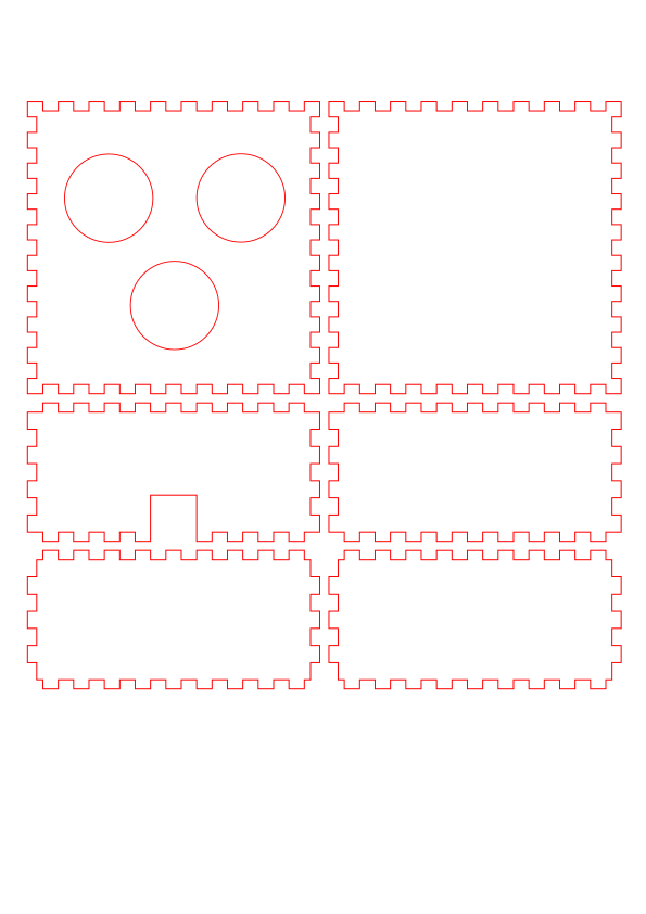
Cut the wood with the laser cutter (laser settings depend on the machine)
Download the svg file for the laser cutter popup:yes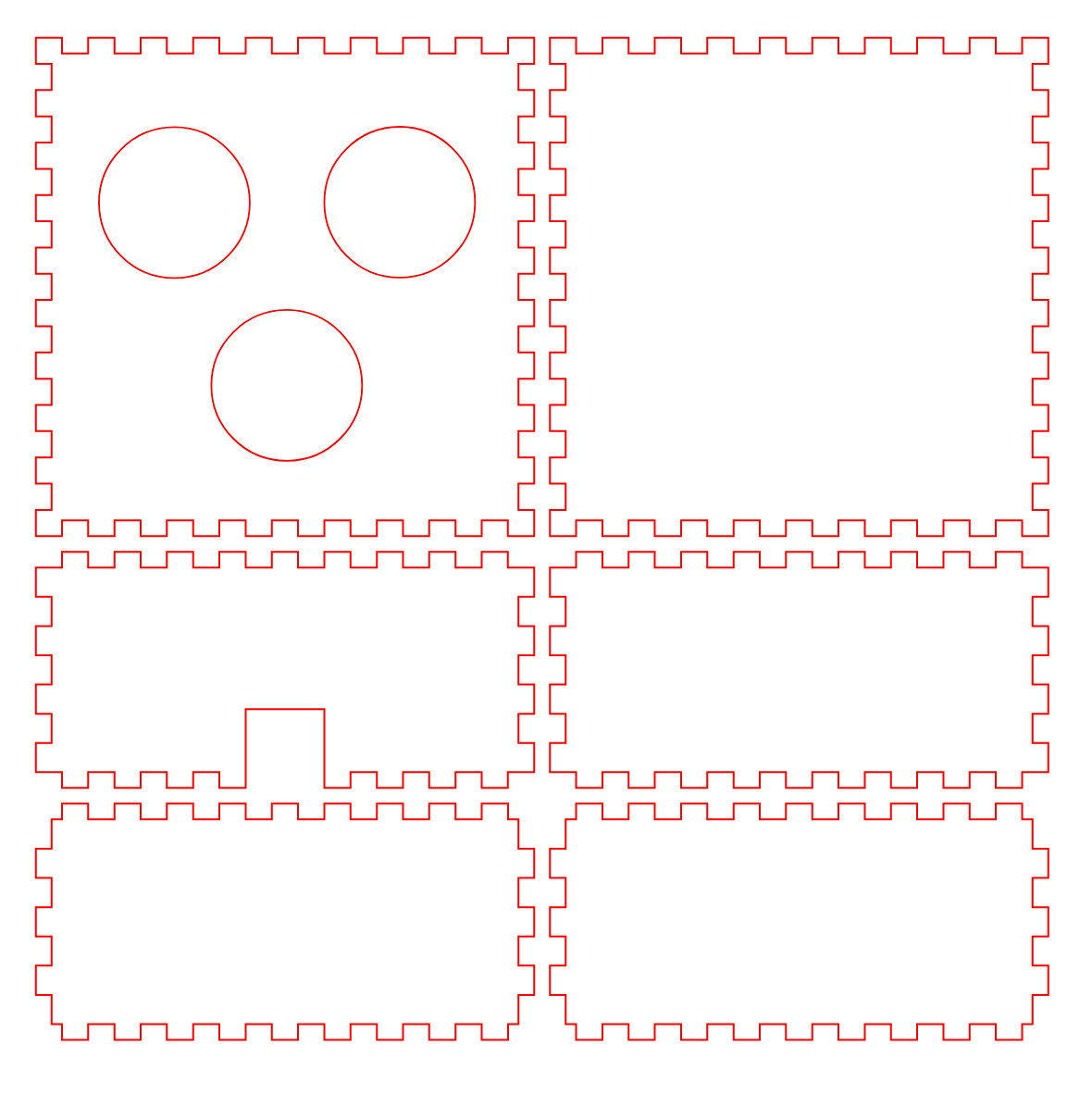
Preview of the svg file -
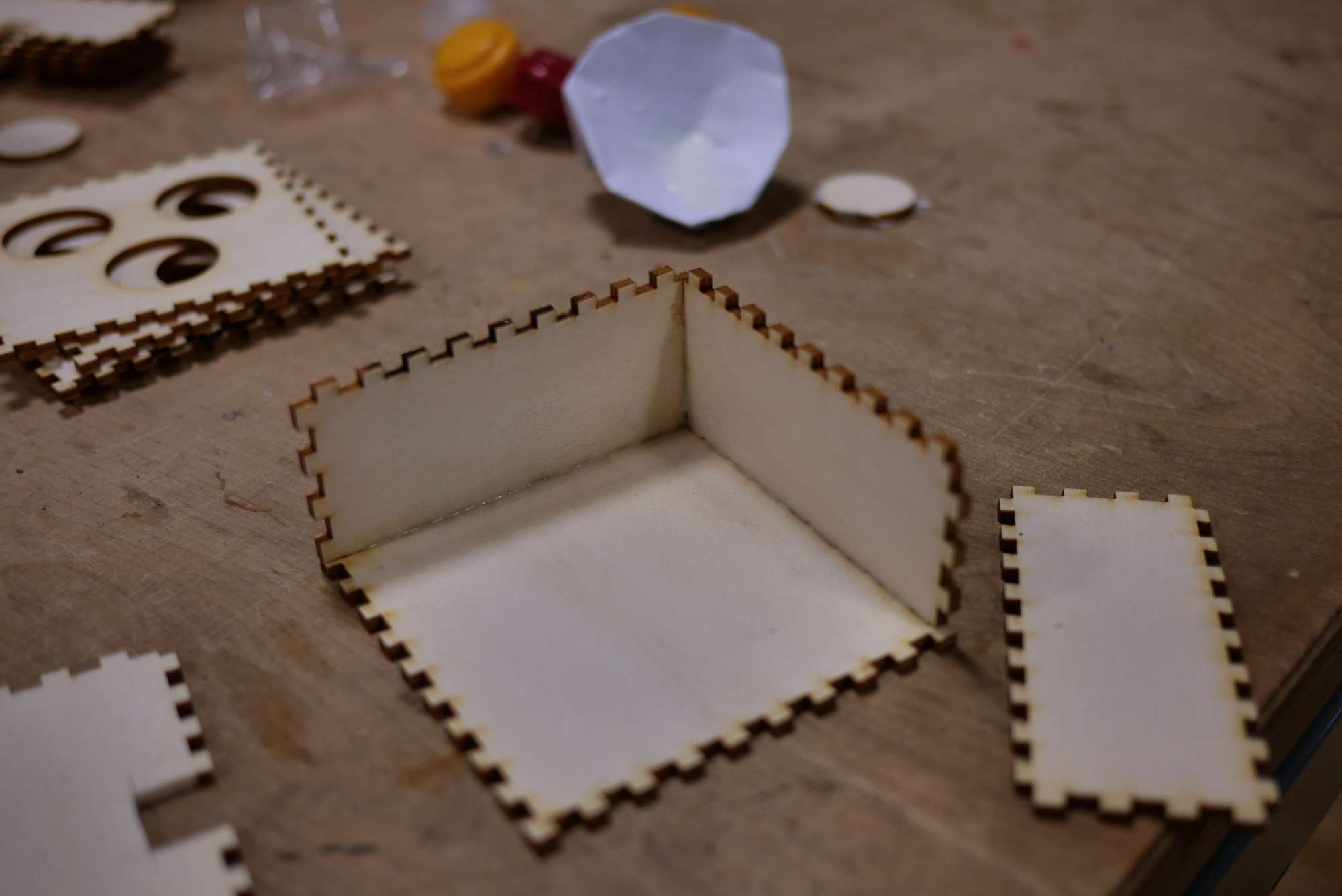
Assemble the bottom and sides of the box and glue them with wood glue

-
Download the dedicated Arduino program (right-click, Save link as…): mobidoc.ino popup: yes
-
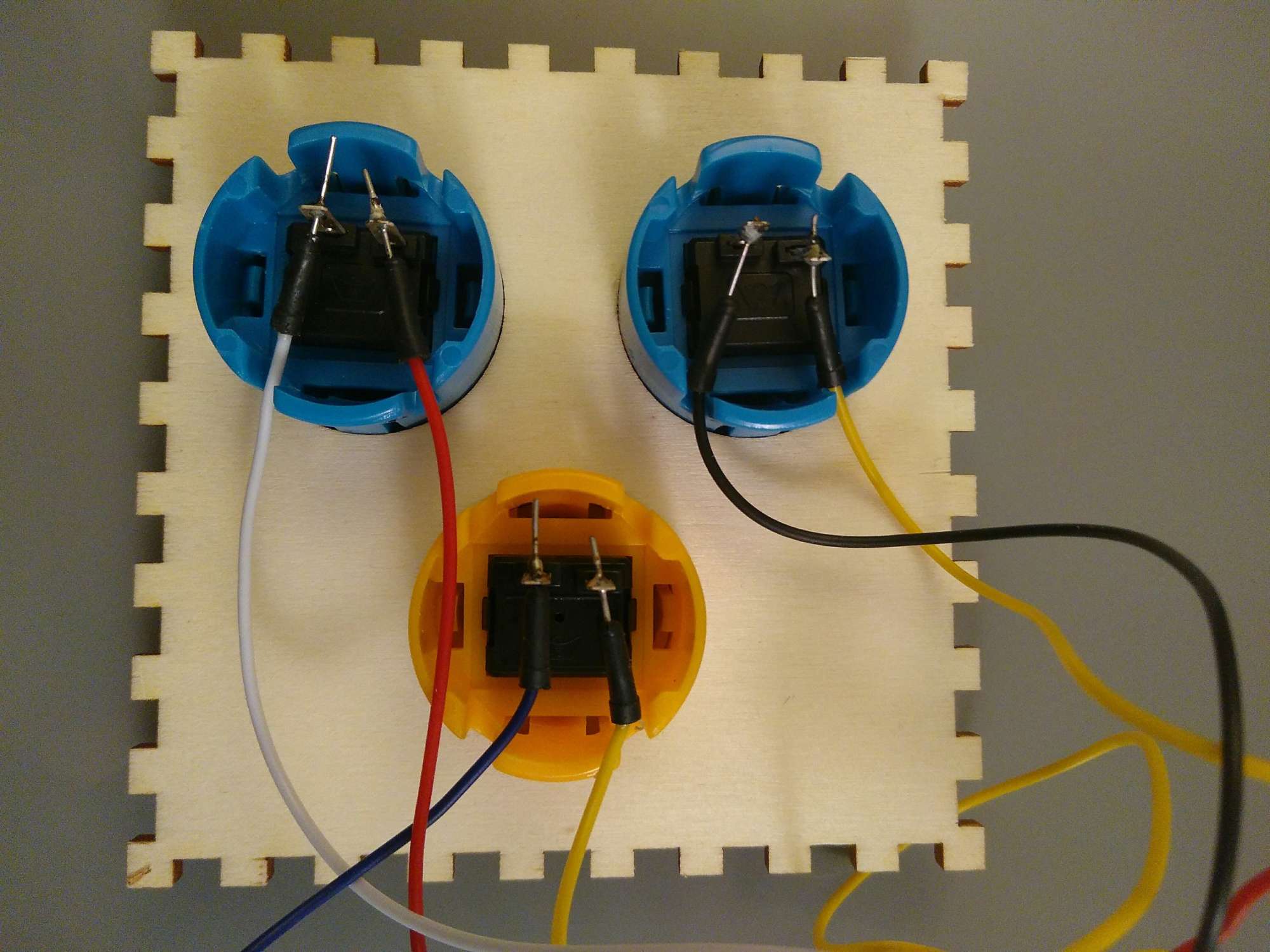
Solder the 3 buttons to the wires, two wires per button, one for - and one for +

-
Insert the buttons into the drilled top part of the box
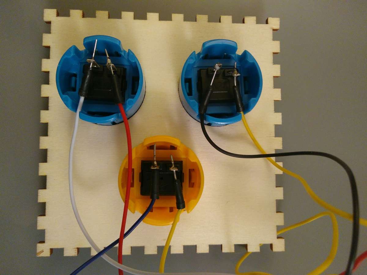
-
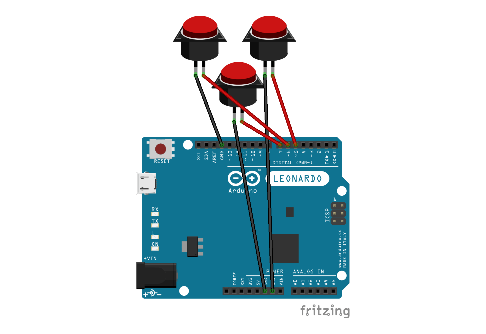
Solder the wires to the Arduino following the diagram (pin 5 for the next button, pin 6 for the previous button and pin 7 for the confirm button)
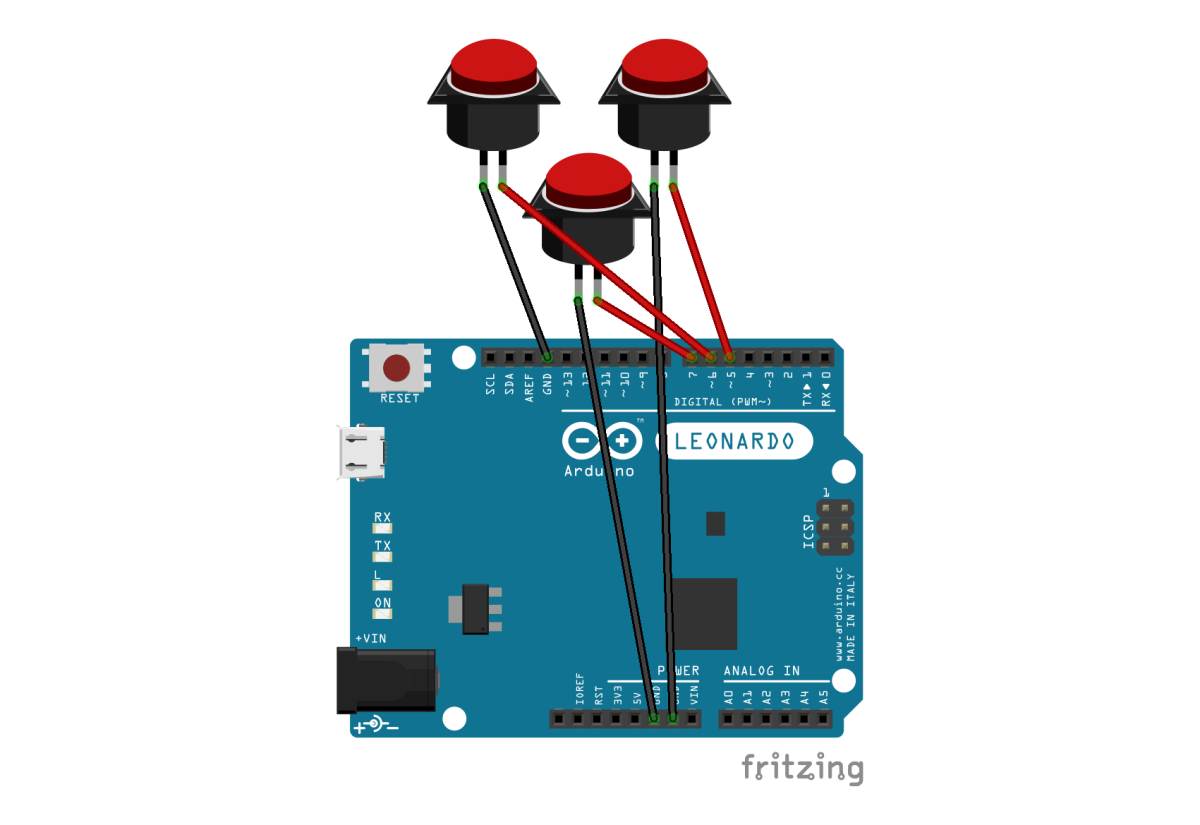
Wiring diagram


- Put everything together
Making the 3D parts
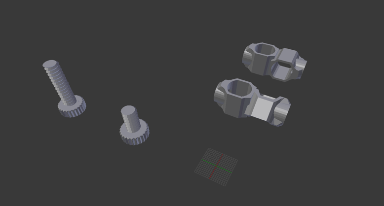
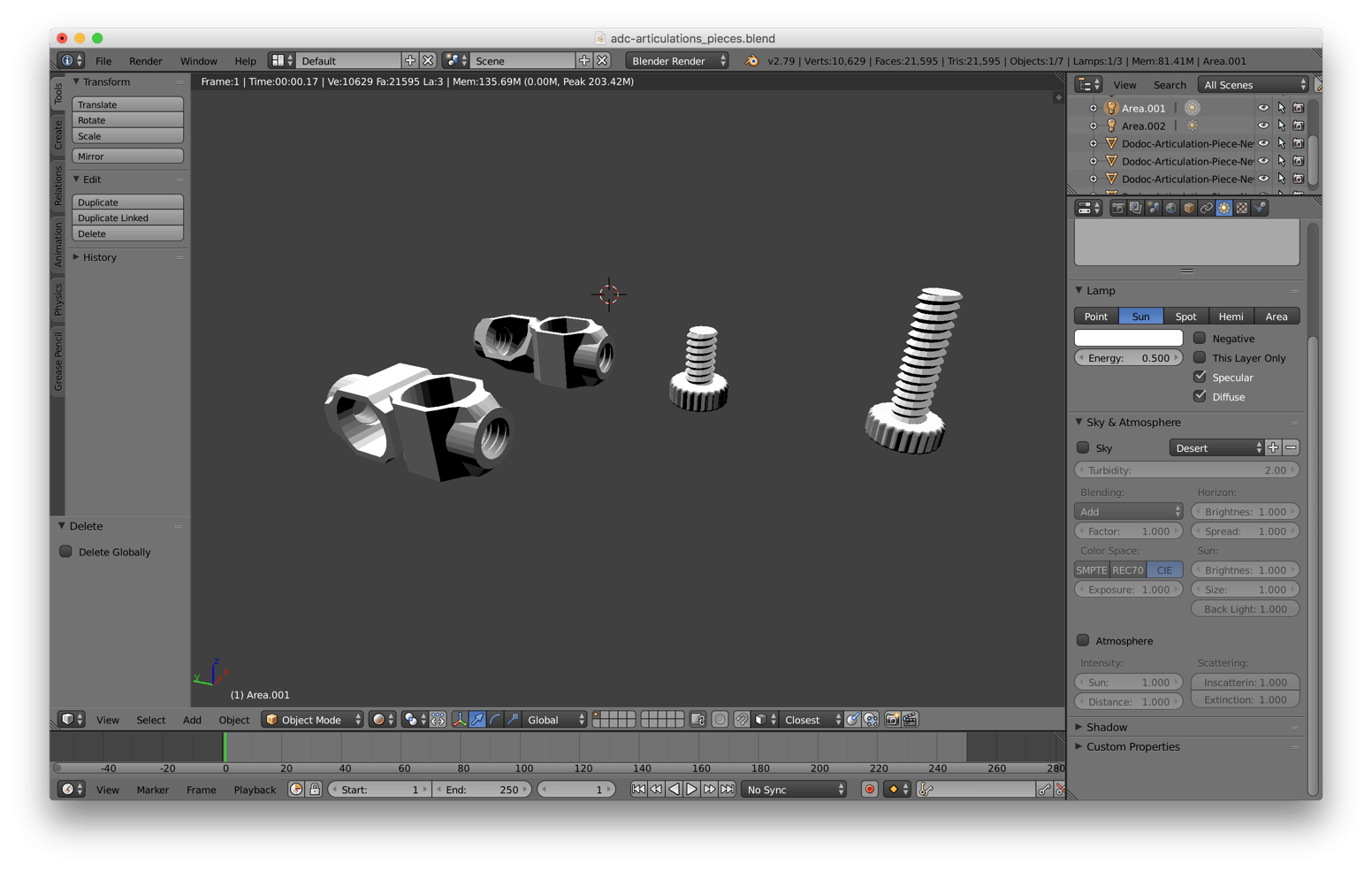
The 3D parts were drawn in Blender and the 3D printing settings are handled by the Cura software. They are used to connect the dowels to each other to build a modular structure for the camera.
These parts are compatible with the parts of the OpenFabrick association, so that more complex structures can be built easily. All OpenFabrick parts are also under a free license.

For the smartphone holder
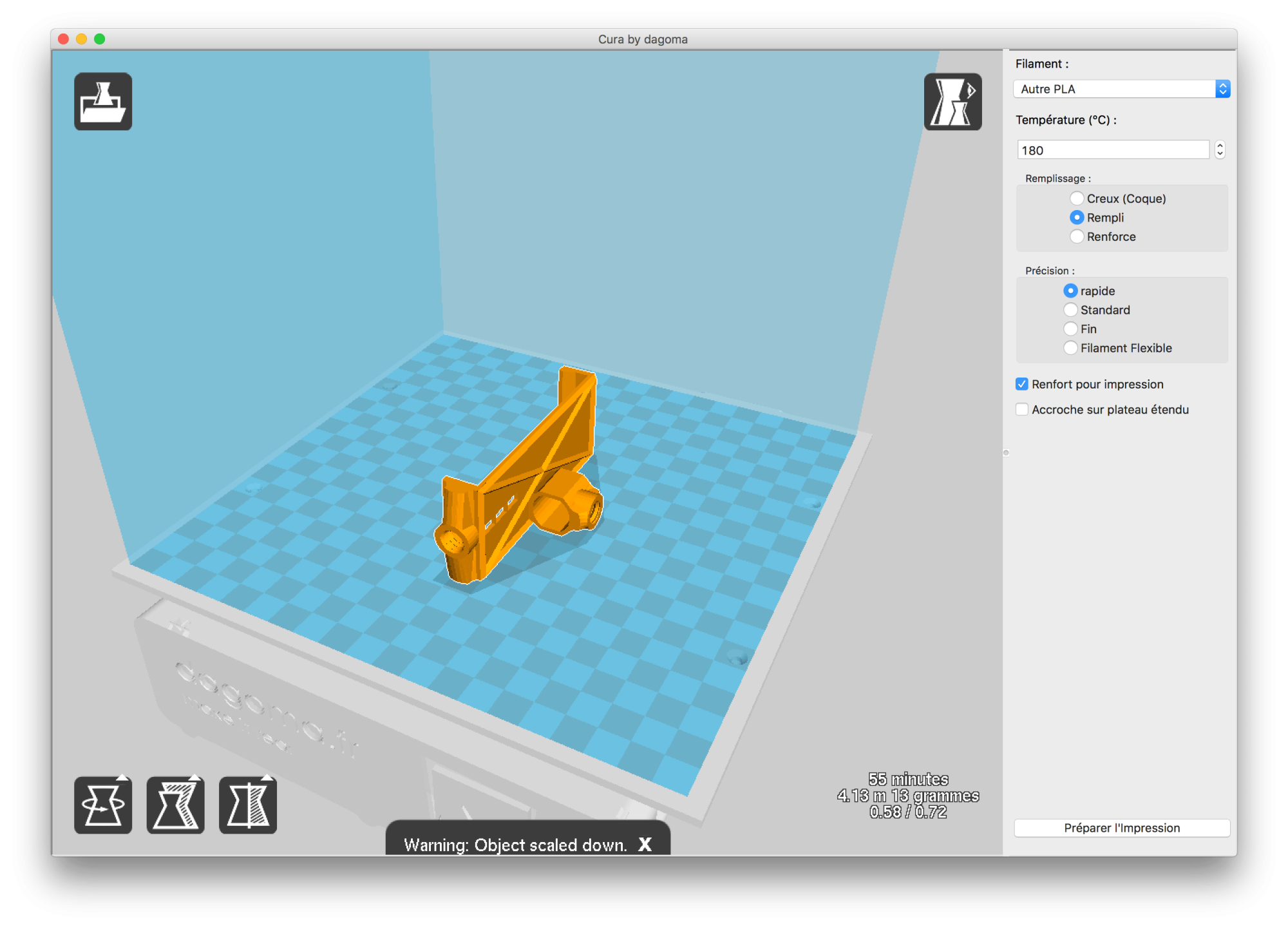
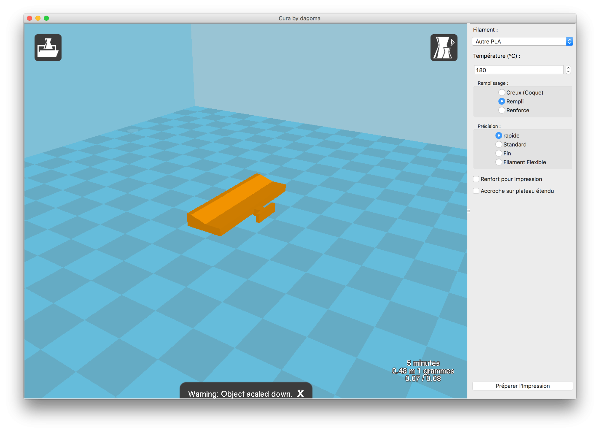
For a documentation station, the best is to have 4 joint parts and a smartphone holder:
- 2 parts for a 90° joint, with 2 short screws for each part
- 2 parts for a 45° joint, with 2 short screws for each part
- 1 smartphone holder with 1 long screw and 1 short screw

The files:
- Blender file with all the joint parts: adc-articulations_pieces.blend
- Blender file of the smartphone holder: dodoc-articulation-support-smartphone-10.blend
STL files (to import into software such as Cura):
- 45-degree part: adc-articulations_pieces-charniere-45deg.stl
- 90-degree part: adc-articulations_pieces-charniere-90deg.stl
- Short screw: adc-articulations_pieces-vis-courte.stl
- Long screw: adc-articulations_pieces-vis-longue.stl
- Smartphone holder, main part: dodoc-articulation-support-smartphone-10-stand.stl
- Smartphone holder, small part used to hold the phone in place: dodoc-articulation-support-smartphone-10-push.stl
Note
With some software and printers, these parts may not print well. If you run into such issues, you can try the parts that Anthony Auffret from Brest made based on ours. Available here: https://www.thingiverse.com/thing:3907809
Cutting the dowels to different lengths
For our station, we use:
- 2 dowels of 50cm
- 2 dowels of 30cm
- 2 dowels of 15cm
- 1 dowel of 10cm
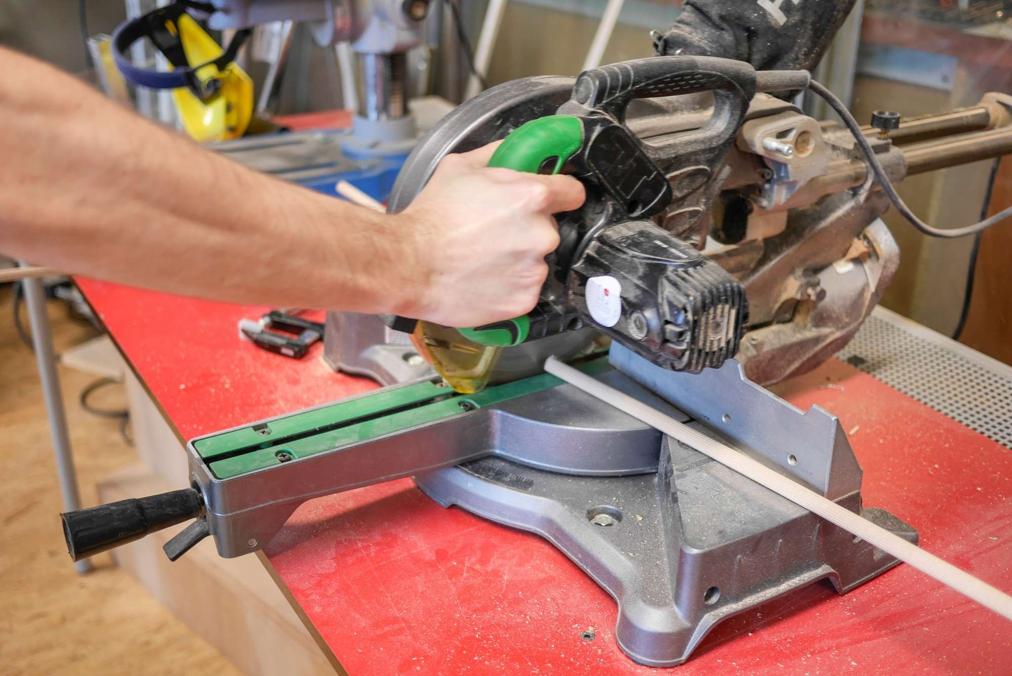
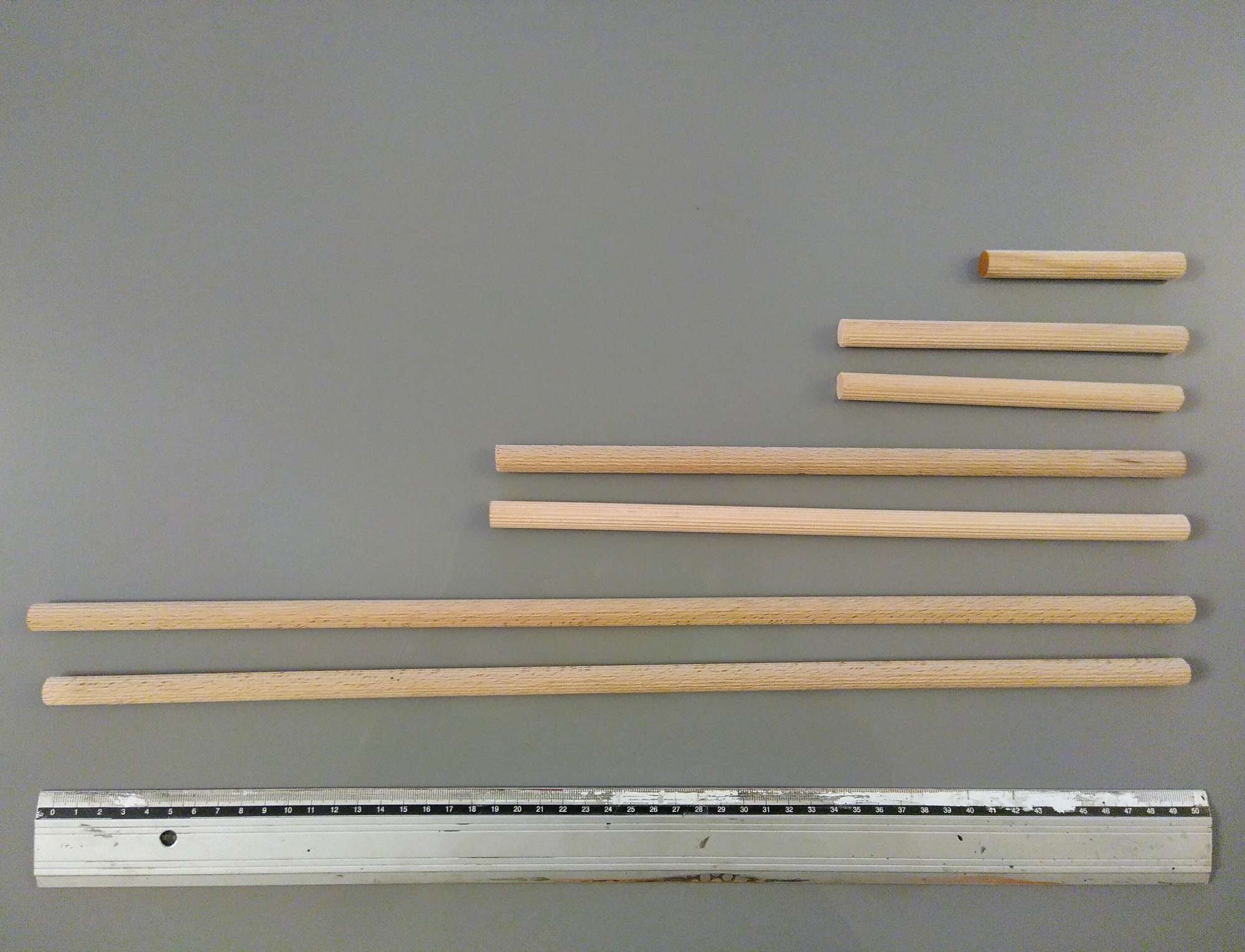
Making the magnetic squares
- Cut 10cm x 10cm squares (if not already done)
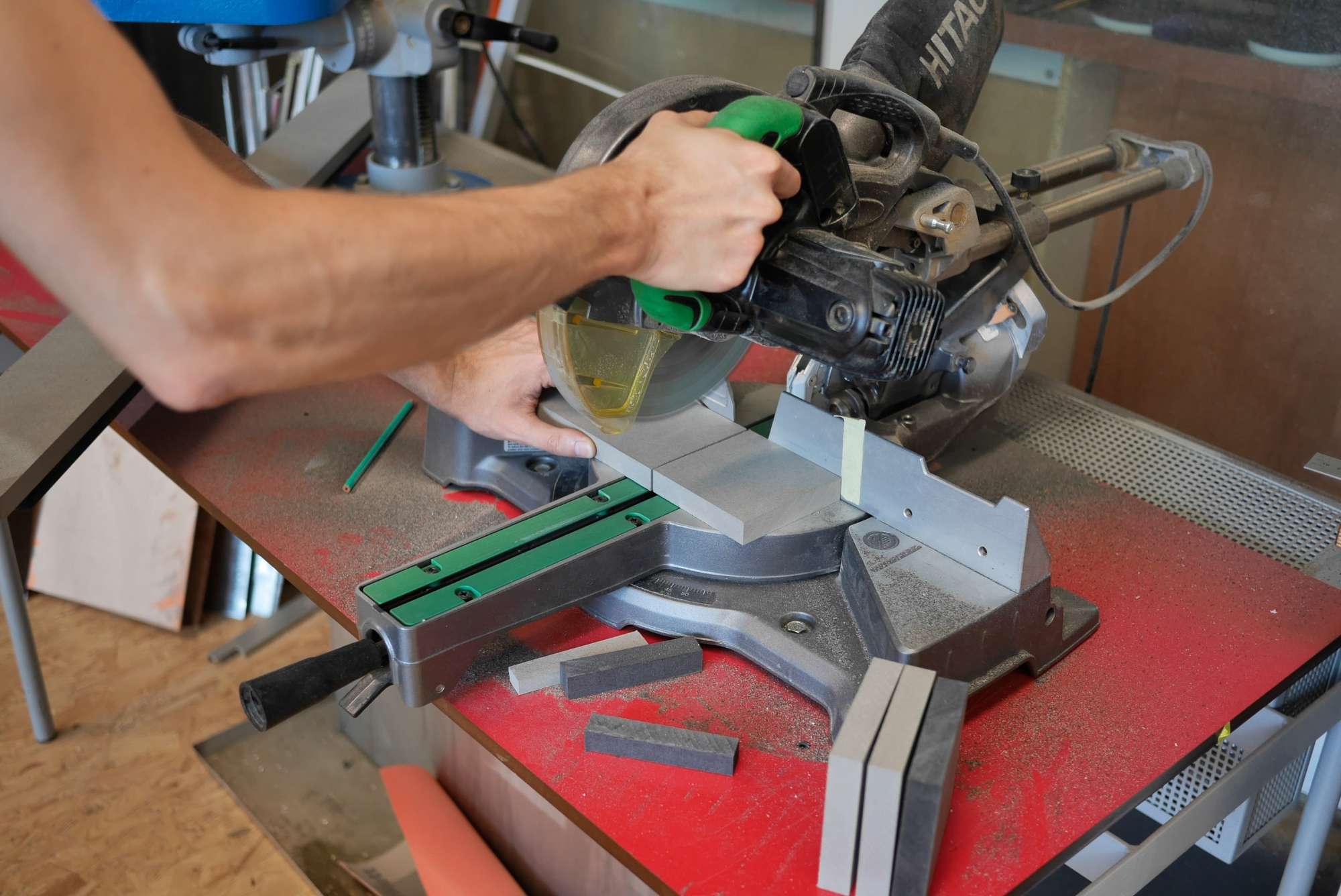
- Mark the center of one face and the centers of all the edges

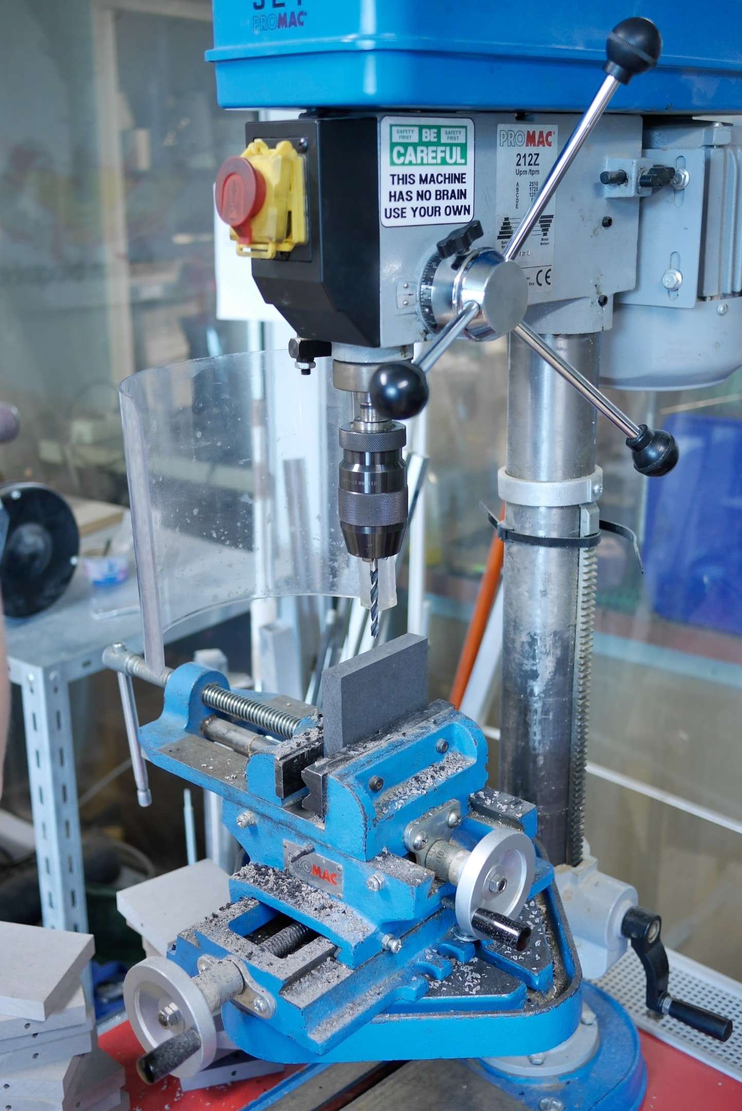
- Drill all the squares in the center with a 12mm drill bit
- Drill 6mm deep holes with a 6mm drill bit in the center of each side (4 holes per square)
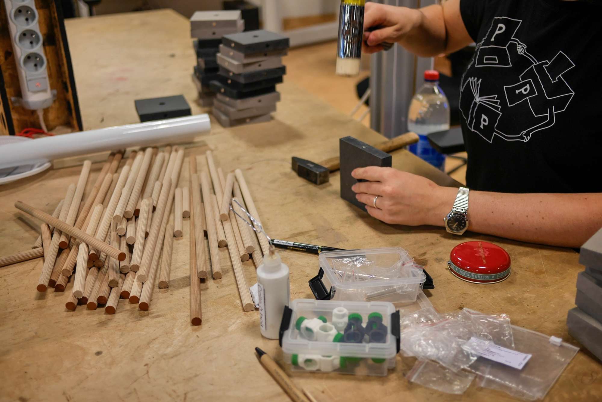
- Using a mallet, push the magnets into the side holes following the diagram below. You can add wood glue if the magnets don’t hold well enough.

Making the board
- Cut the board to 30cm x 40cm
- Drill 4 holes along the length (at 5, 15, 25 and 35cm from the edge) and 3 holes along the width (at 5, 15 and 25cm from the edge), 6mm deep, with a 6mm drill bit.

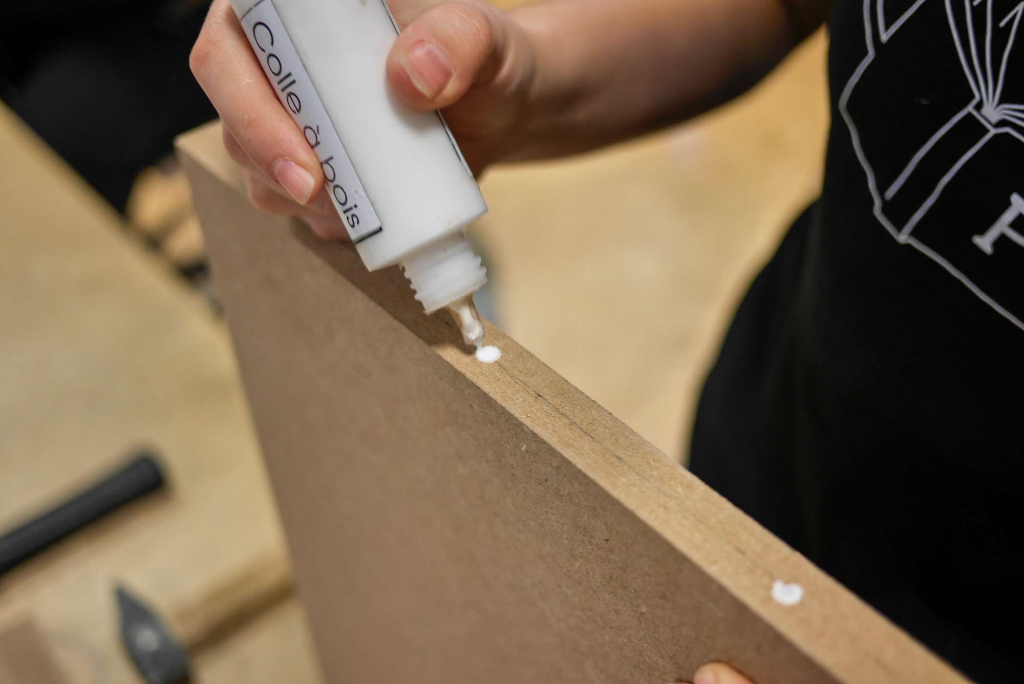
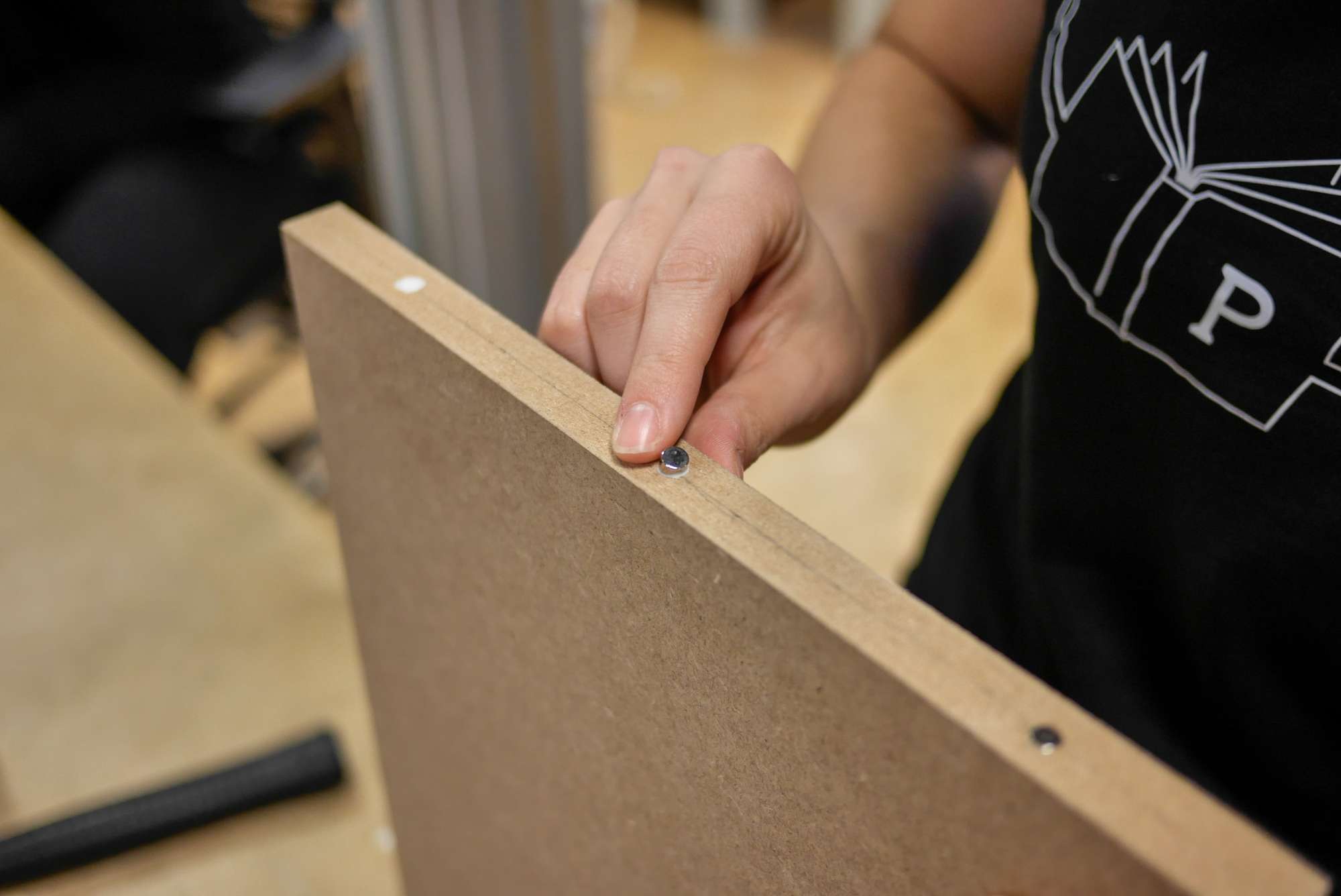
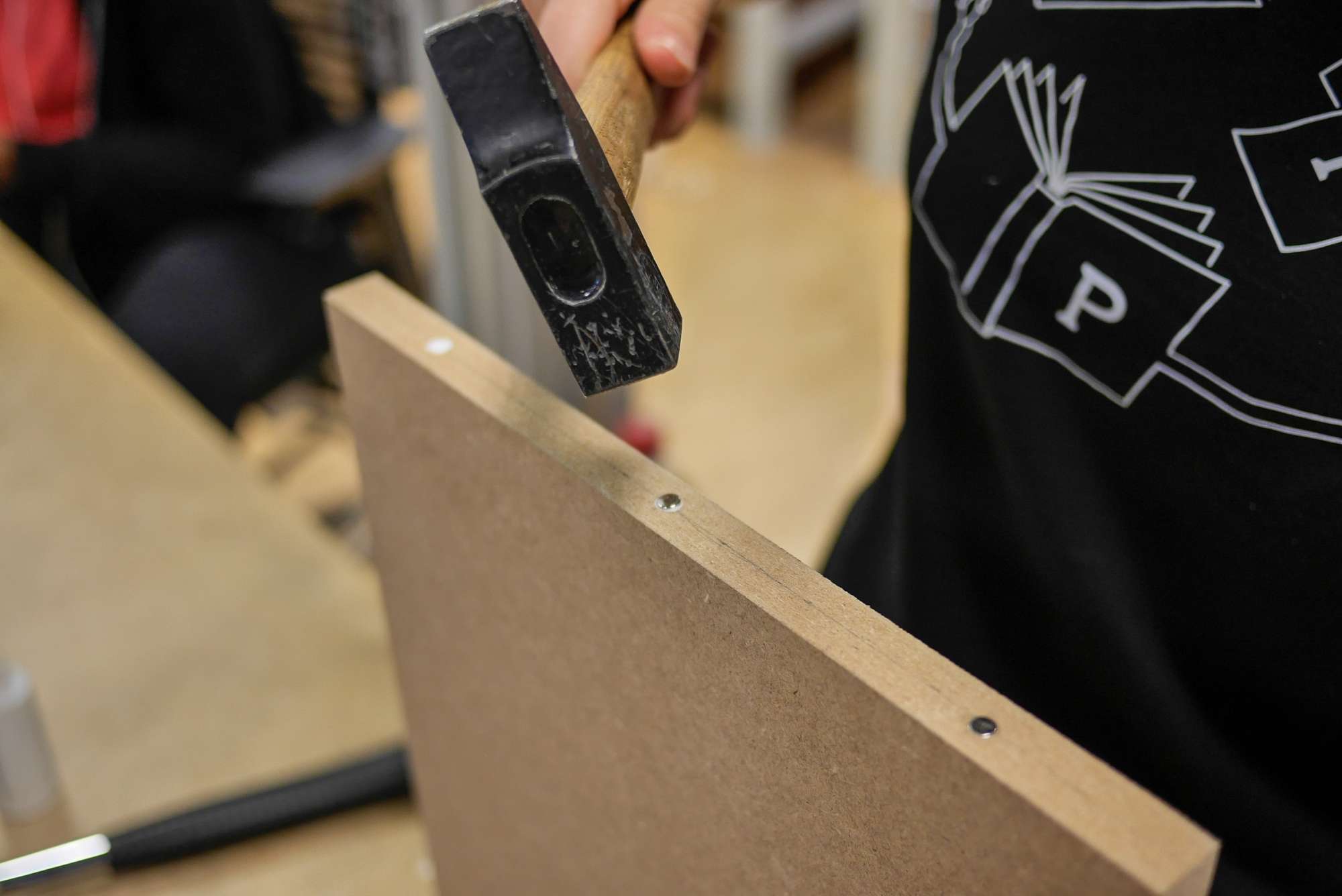
- Using a hammer, push the magnets into the holes on all sides. All magnets must face the same way, minus side out. You can add wood glue if the magnets don’t hold well enough.

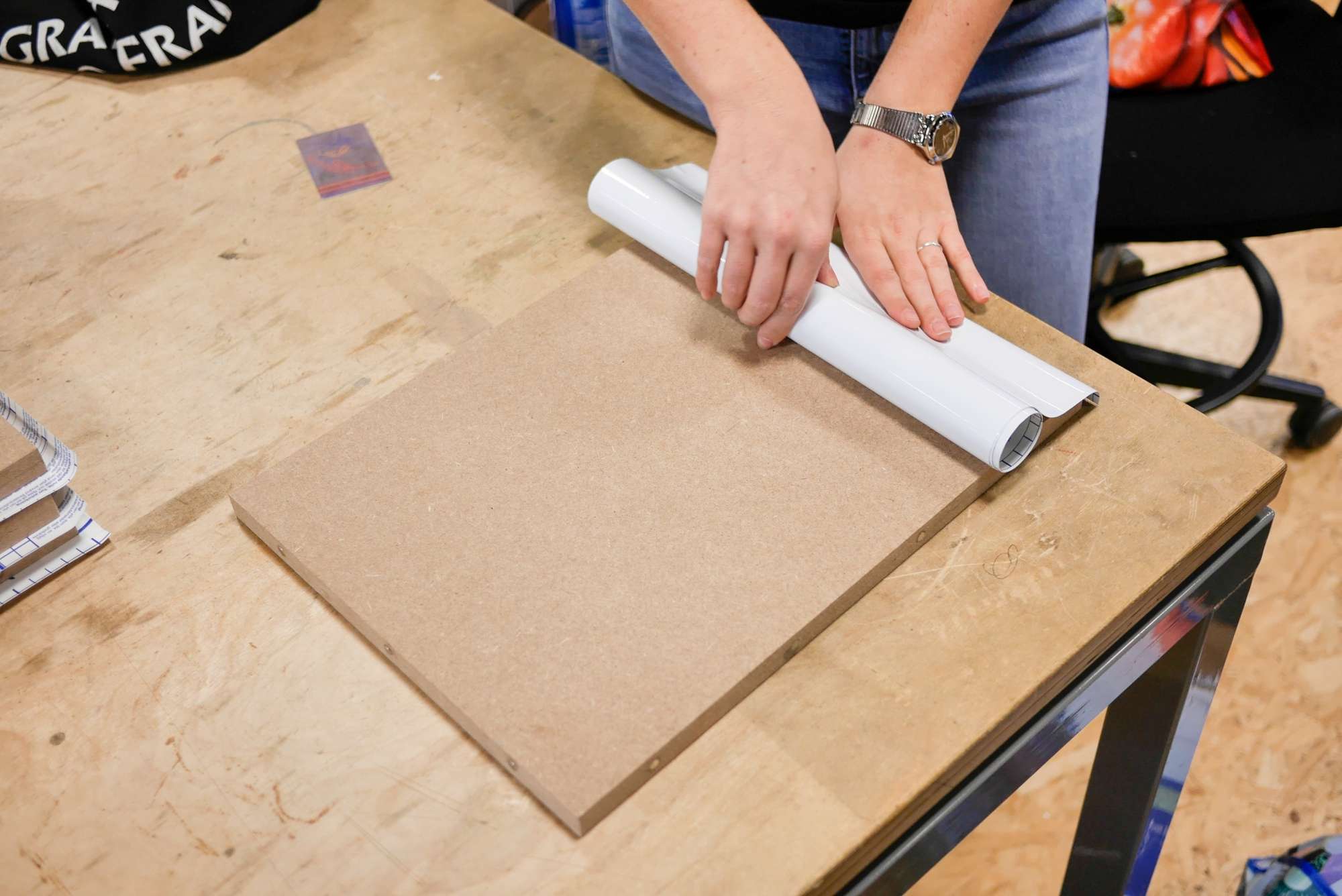
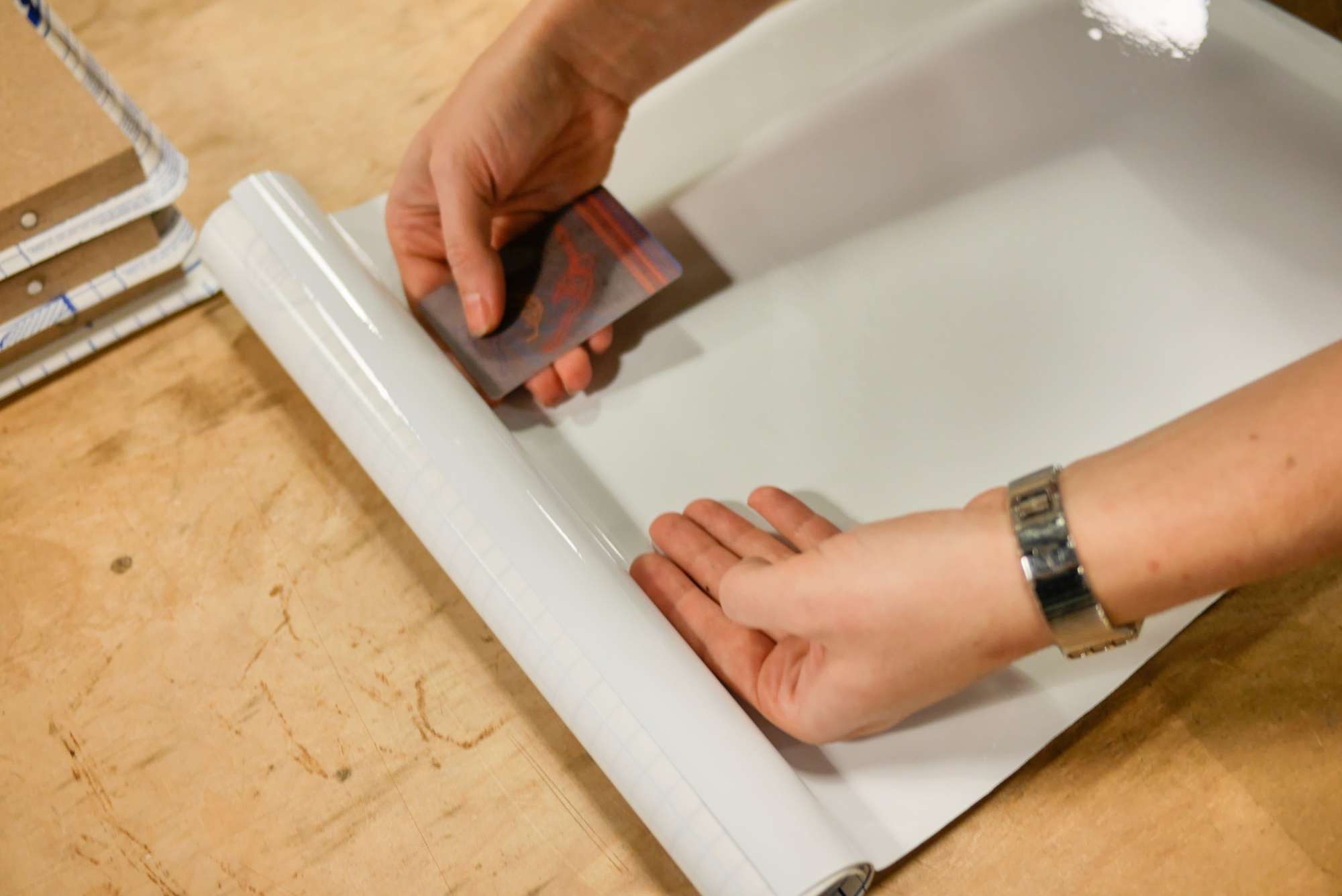
- Stick the whiteboard film on one side of the board
Assemble the station according to your needs and wishes


Thanks
Most of the photos of wood cutting and assembly were taken at the Carrefour Numérique, the fablab of the Cité des Sciences in Paris. Thanks to its team for their kindness and help.